- Quick Attack Highlight
- Summary
- 1. Background
- 1.1 ArUco-based UAV Precision Landing
- 1.2 Research Gap and Novelty
- 1.3 Threat Model
- 2. MirageMarker
- 2.1 Design Challenges and Solutions
- 2.2 Attack Pipeline
- 3. Evaluation
- 3.1 End-to-End Landing Demos
- 3.2 Key Results
- Research Paper
- Team
- Acknowledgments
Quick Attack Highlight
Same UAV, same unmodified PX4 precision-landing mode in NVIDIA Isaac Sim (grid board); only the landing board differs. Distances are mean touchdown errors.
Summary
ArUco markers guide UAVs during the final stage of precision landing, including in delivery systems such as Google Wing and Meituan. Prior robustness studies focus on marker detection under poor lighting or occlusion. The accuracy of the resulting pose estimate under changes to marker geometry has received less attention.
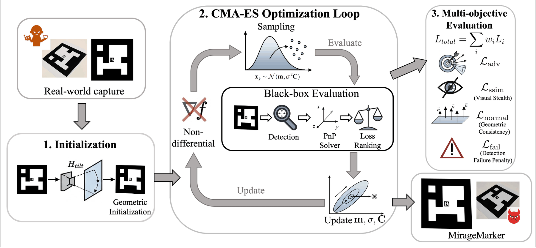
We present MirageMarker, a black-box attack on ArUco-based UAV landing. It introduces small shifts to marker corners while preserving decoding and visual similarity. We use black-box multi-objective optimization to find these shifts because the ArUco detection–PnP pipeline is non-differentiable.
In NVIDIA Isaac Sim, using PX4's unmodified precision-landing mode, the mean touchdown error increases from ≤ 0.03 m with clean boards to 8.12–12.37 m under attack. The attacks remain effective in our tests with RANSAC and a Kalman-filter χ² gate.
1. Background
1.1 ArUco-based UAV Precision Landing
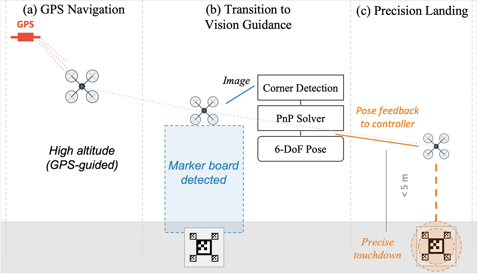
Near the ground, GPS is not accurate enough for a precise touchdown. Once the landing pad is in view, the UAV switches to a downward camera: it detects the ArUco markers, localizes their four corners, and solves Perspective-n-Point (PnP) for its 6-DoF pose relative to the pad. The pose is fed back to the flight controller until touchdown.
1.2 Research Gap and Novelty
- Detection robustness and pose accuracy. Prior ArUco studies address detection under poor lighting, occlusion or motion blur. We examine how small corner offsets affect the pose estimate even when the marker is detected.
- A non-differentiable pose pipeline. Gradient-based attacks on deep-learning perception models cannot be applied directly to the ArUco corner-detection and PnP pipeline. Our attack modifies the marker board itself, without injecting data into the UAV's sensing channels.
- Corner geometry determines the pose estimate. The bit pattern identifies the marker; PnP estimates pose from the detected corners and known marker geometry. In our sensitivity study, shifts within a 1 cm radius at one corner of a 10 cm marker can produce > 5 cm translation error and > 20° rotation error (Figure 2), exceeding the 5 cm / 5° thresholds used in our evaluation.
- Novelty. To our knowledge, MirageMarker is the first systematic study of fiducial-marker pose estimation under adversarial manipulation of marker geometry, with an end-to-end evaluation in UAV precision landing.

1.3 Threat Model
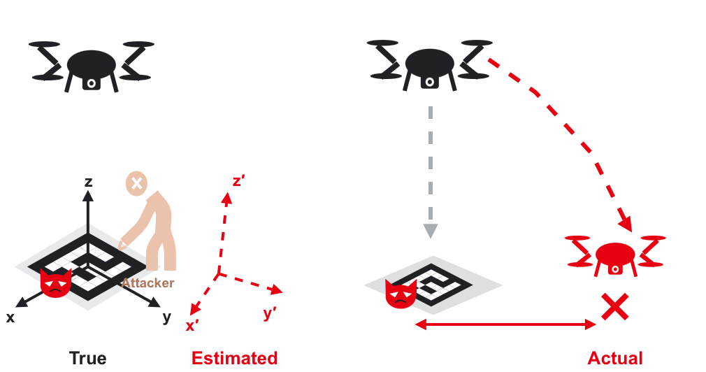
- Physical access to an open landing pad. The attacker replaces or overlays the pad with a printed adversarial board; delivery landing pads are often in open, physically accessible areas.
- Knowledge of the board and the camera. The board layout can be observed on site; camera model and intrinsics can be obtained from manufacturer documentation or by buying the same platform.
- No system access. No access to the UAV's flight software, onboard sensors, or controller.
- Attack window. The final landing phase (below 5 m), when the UAV relies on ArUco-based vision.
2. MirageMarker
2.1 Design Challenges and Solutions
Preserving marker detection and appearance
The attack must bias the estimated pose while preserving marker decoding and visual similarity to the original board.
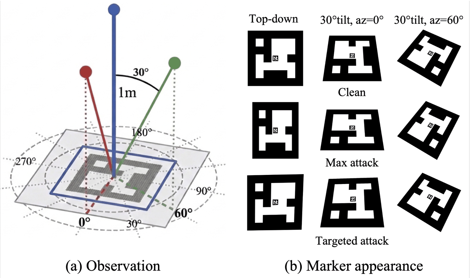
Solution: small corner shifts with detection and visual constraints. Corner shifts are bounded, and the marker IDs are preserved. A penalty rejects candidates that fail detection or pose estimation, while multi-view SSIM limits visible changes to the board.
Optimizing a non-differentiable pipeline
The ArUco detector and PnP solver do not provide gradients for end-to-end optimization of the marker corners.
Solution: black-box multi-objective optimization. The attack is encoded as the 2D shifts of every marker corner (8 values per marker), bounded so markers stay printable and never overlap. Each candidate board is scored by running the real ArUco detection and PnP pipeline on rendered views, with one score that combines the attack goal, stealth (SSIM), planar consistency, and a detection-failure penalty. CMA-ES searches this space from a homography-based geometric seed.
Maintaining pose bias during descent
As the UAV descends, its view of the board changes. The pose bias must persist across these views to affect the landing trajectory.
Solution: two attack objectives. The Directional Max Attack (DMA) pushes the estimated position along a hazardous direction. The Targeted Frustum Attack (TFA) drives the estimated horizontal offset toward zero from viewpoints sampled inside a frustum along a target azimuth, so the UAV believes it is approaching the pad centre and keeps flying that way.
2.2 Attack Pipeline
3. Evaluation
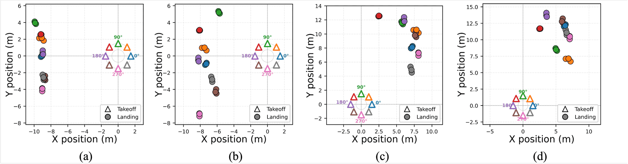
We evaluate end-to-end landing in NVIDIA Isaac Sim using PX4's unmodified native precision-landing mode (AUTO.PRECLAND). We test two common board layouts: a nested board and a 3 × 3 grid board. Each trial starts with the UAV 1.5 m horizontally from the pad centre. It ascends to 5 m before switching to precision landing. We test eight initial azimuths.
3.1 End-to-End Landing Demos
Clean boards. The UAV approaches, descends, and touches down on the pad.
Mean touchdown error: 0.03 m (nested), 0.02 m (grid).
DMA (push). The biased pose pushes the UAV sideways until the board leaves the camera view. PX4 climbs to search, does not find the board again, and lands far from the pad.
Mean touchdown error: 9.48 m (nested), 8.12 m (grid).
TFA (pull). The pose estimator reports almost no horizontal offset, so the UAV continues along the target azimuth until the board leaves the camera view. It then searches for the board and lands away from the pad.
Mean touchdown error: 11.9 m (nested), 12.37 m (grid).
3.2 Key Results
mean touchdown error with clean boards
mean touchdown error under MirageMarker
of attack trials in our evaluation end outside the pad and more than 5 m away
of attacked vision updates reaching PX4's χ² gate are accepted
In these simulations, centimetre-scale corner shifts produce metre-scale touchdown errors on both layouts. RANSAC retains most perturbed corners as inliers, and the Kalman-filter gate accepts more than 96% of the attacked vision updates that reach it.
Research Paper
[IROS'26] MirageMarker: A Black-Box Pose Estimation Attack for Autonomous UAV Landing
Junchi Lu, Fayzah Alshammari, Shaoyuan Xie, Xiaoqing Liang, Qi Alfred Chen
IEEE/RSJ International Conference on Intelligent Robots and Systems (IROS), 2026.
[PDF] [Code] [Overview Video] [Poster]
@inproceedings{lu2026miragemarker,
  title={{MirageMarker: A Black-Box Pose Estimation Attack for Autonomous UAV Landing}},
  author={Lu, Junchi and Alshammari, Fayzah and Xie, Shaoyuan and Liang, Xiaoqing and Chen, Qi Alfred},
  booktitle={IEEE/RSJ International Conference on Intelligent Robots and Systems (IROS)},
  year={2026}
}
Team
- Junchi Lu, Ph.D. student, University of California, Irvine
- Fayzah Alshammari, Ph.D. student, University of California, Irvine
- Shaoyuan Xie, Ph.D. student, University of California, Irvine
- Xiaoqing Liang, Ph.D. student, University of California, Irvine
- Qi Alfred Chen, Associate Professor, University of California, Irvine
Acknowledgments
This research was supported by:
- NSF under grant CNS-2145493;
- NASA University Leadership Initiative under Award 80NSSC24M0070.